
Objective
Configure the SocketAdapter component as a Server in synchronous mode and configure it as a Client to invoke the server.
Prerequisites
-
Start Fiorano Enterprise Server (FES) and Fiorano Peer Server (FPS)
-
Login to eStudio application
-
Understand the basic menus and perspectives (panels) in eStudio application
Scenario
Create a Socket Server with a specific Port number and IP address to listen to Socket Client data. The server receives the data that is sent by the Client. Socket Server writes back the data to the Socket Client and indicates the successful write-back process through a status message.
Components used
-
Two SocketAdapter components
-
Three Display components
-
One Feeder component
Setting up the Example
Socket Server Configuration
To configure SocketAdapter component for the server, perform the following action in eStudio:
-
Add a new Event Process with the name 'SocketRW_Server_Eg'.
-
Drag the SocketAdapter component from Bridges category in the Micro Service Palette to the Fiorano Orchestrator.
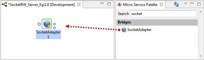
Figure 1: Adding SocketAdapter compoent to Fiorano Orchestrator
-
Click the SocketAdapter component and do any of the following to rename the component from 'SocketAdapter' to 'SocketServer':
-
Press F2, change the name, and click OK.
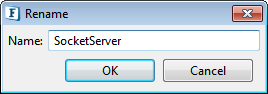
Figure 2: Renaming using Keyboard action 'F2'
-
Go to Name property under General tab in Properties, change the name, and press ENTER.

Figure 3: Renaming using General Properties
The name change is to distinguish it from the Socket that will be configured for the client.
-
-
Double-click the SocketServer component in the Orchestrator to open the Configuration Property Sheet (CPS).
-
Click the Attributes tab and provide the following values:
-
Select the Create Socket ? check box.
-
Server IP: 127.0.01 (retain default IP)
-
Port: 5436 (retain default port)
-
Decoding Type: None
This will start SocketServer on the peer server machine at port 5436.
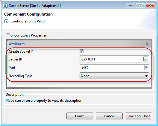
Figure 4: SocketServer Configuration in CPS
-
-
Click Finish to save the server configuration.
Socket Client Configuration
To configure SocketAdapter component for a client, perform the following action in eStudio:
-
Add a new Event Process with the name 'SocketRW_Client_Eg'.
-
Add SocketAdapter component to Fiorano Orchestrator and change the name to 'SocketClient' by following the steps mentioned in Socket Server Configuration section.
-
Open SocketClient component CPS, click the Attributes tab, and provide the following values:
-
Leave the Create Socket ? check box unchecked.
-
Server IP: 127.0.01 (same IP as used in Server Configuration)
-
Port: 5436 (same port as used in Server Configuration)
-
Decoding Type: None
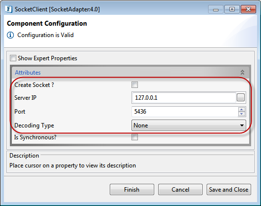
Figure 5: SocketClient Configuration in CPS
-
-
Click Finish to save the client configuration.
Composing Server Event Process
-
In the SocketRW_Server_Eg Event Process Orchestrator, perform the following actions:
-
Connect the SocketServer output port to the SocketServer input port
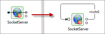
Figure 6: Connecting SocketServer input port to output port
-
-
Drag two Display components from Util category to the Orchestrator.
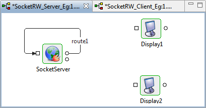
Figure 7: Adding Display components to SocketRW_Server_Eg event process
Connect the Display components to the SocketServer and rename them to match the SocketServer output port names in the following manner:
-
Connect Display1 to SocketServer OUT_PORT and rename it to DisplayMessage.
-
Connect Display2 to SocketServer STATUS_PORT and rename it to DisplayStatus.
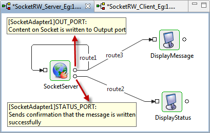
Figure 8: Connecting Display components to SocketServer
Composing Client Event Process
In the SocketRW_Client_Eg Event Process Orchestrator, perform the following actions:
-
Drag one Feeder and one Display component from Micro Service Palette under Util category.
-
Connect the components in the following manner:
-
Feeder component output port to SocketClient input port.
-
SocketClient output port to Display component input port.
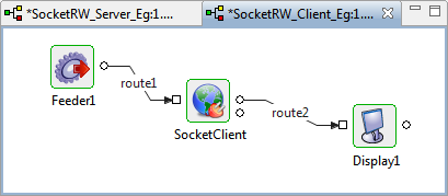
Figure 9: Adding Display components to SocketRW_Client_Eg event process -
Understanding the Data Flow
Data flows in the following order:
-
Feeder sends data to SocketClient.
-
SocketServer receives the data from ServerClient and displays it in DisplayMessage.
-
SocketServer redirects the data back to SocketClient and displays the successful write-back status in DisplayStatus.
-
SocketClient receives the data back from the server and displays it in Display1.
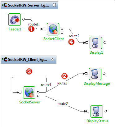
Figure 10: Data flow between SocketServer and SocketClient
Running the Example
Open SocketRW_Server_Eg Event Process Orchestrator and perform the following actions:
-
Click Check Resource and Connectivity icon (or press ALT+SHIFT+C) to check resource and connectivity.
-
Click Run Event Process icon (ALT+SHIFT+R) to run the event process. DisplayMessage and DisplayStatus windows get open.
-
Switch to SocketRW_Client_Eg Event Process Orchestrator and follow steps 1 and 2 above. Feeder1 and Display1 components get open.
-
In the Client Feeder1 window, replace 'Input Text' with 'TestMessage' and click Send.
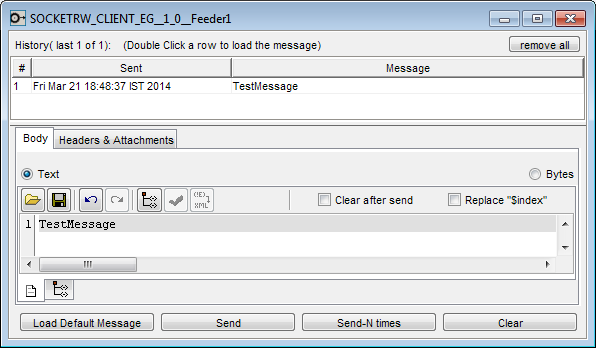
Figure 11: Sending a message from Feeder
-
DisplayMessage window displays the message from the client that is received by the server.
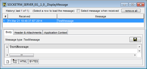
Figure 12: Displaying Message received from client
-
DisplayStatus shows the confirmation message 'Message Sent Successfully' as the server writes the message back to the client.
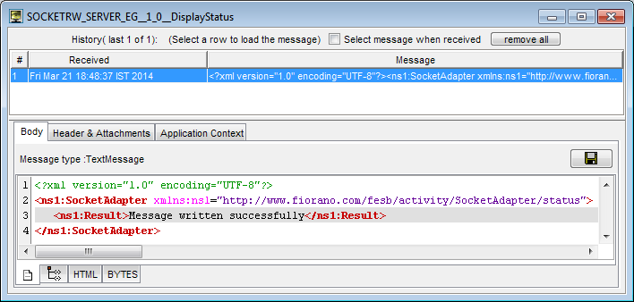
Figure 13: Status message indicating that message is written back to the client
-
Display1 receives the message that is sent back from the server.
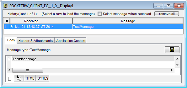
Figure 14: Message sent back by Server, received by the client
Reference
-
Download SocketRW_Server_Eg and SocketRW_Client_Eg event processes and Import the Event Processes to the Event Process Repository in the Server Explorer in eStudio to understand the configuration used in this example and to execute the working sample.
-
Please note that the options used in this example are minimal, which helps you to get an overview of the application. To explore the other options present in the SocketAdapter, Feeder and Display, refer to sections: SocketAdapter, Feeder and Display respectively.