Creating Mappings
Mappings are defined between nodes of the Input and Output structures. The Structure is displayed in a tree form.
Understanding Types of Nodes
Mappings are defined between nodes of the Input and Output structures. These nodes can be divided into four types:
- Element Node: This type of node contains an XML element.
- Text Node: This type of node contains an XML element only.
- Attribute Node: This type of node contains an attribute of the XML element that contains it.
- Control Node: The control node is a pseudo node that depicts the cardinality of the elements in an XML structure. The Control node is displayed in red color and is surrounded by square brackets.
The control node serves as a useful indicator while creating mappings between the Input and Output Structures. For example, an Output structure node that has a cardinality of one or more requires that at least one element should be added to that XML structure.
Control Node[ZERO-MANY]: This Control node specifies that zero to many occurrences of a node can exist in its parent node. For example, in the figure below, the Mail-List element can contain zero or many Mail nodes.
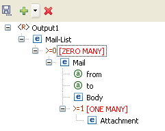
Figure 1: Example of Zero to Many control node
Control Node [ONE-MANY]: This Control node specifies that one to many occurrences of a node can exist in its parent node. For example, in the figure below, the Mail node can contain one or many occurrences of the Attachment node.
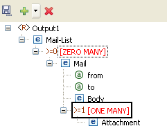
Figure 2: Example of One to Many control node
Control Node [Choice]: This Control node specifies that only one of the descendant nodes can exist in the parent node. For example in the figure below, TifosiService node can have either Java node or Win32 node.
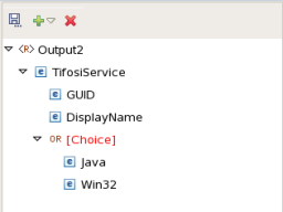
Figure 3: Example of Choice Control Node
A structure can also contain optional nodes. This type of node specifies that either zero or one occurrence of this node can exist in its parent node. For examples, in the figure below, Student node can have either zero or one occurrence of the Nick-Name node. An Optional node (element/attribute) is displayed in green color.
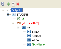
Figure 4: Example of Optional Node
Types of Mappings
Mappings from an Input Structure node to an Output Structure node can be singular or iterative. Singular mappings, known as Name-to-Name mappings in Fiorano Platform, create only one output element from the first instance of the mapped element in the Input Structure.
On the other hand, iterative mappings, known as For-Each mappings in Fiorano Platform, iterate through all instances of the mapped Input Structure element and create corresponding Output Structure elements. For Input Structure nodes that contain only single instances of child elements, only Name-to-Name mappings can be defined.
Name-to-Name Mapping
Now create mapping from Name-to-Name, as shown in the figure below.
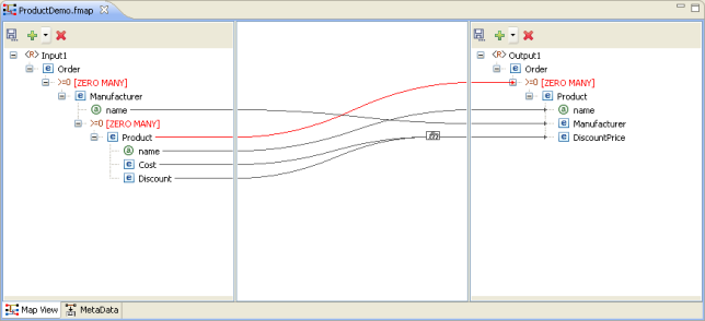
Figure 5: Name-to-name Mapping
The Funclet wizard shows a link starting from the output of the name input node to name output node. The Name-to-Name mapping defines how elements and attributes in the Input Structure map on to elements and attributes in the Output Structure. A Name-to-Name mapping on its own (without a For-Each mapping context) creates a single instance of the mapped Input Structure node to the Output Structure.
If the Name-to-Name mapping exists within a For-Each mapping context and there are multiple elements and attributes in the Input Structure then each of those elements and attributes is mapped on to an Output Structure node.
For-Each Mapping
When an Input Structure node can have multiple instances and the user wants to define a mapping for each one of them, then For-Each mapping should be used. A necessary condition for this type of mapping is that the Output Structure node to which For-Each Mapping is being defined should be of[ZERO-MANY] or [ONE-MANY] cardinality. The figure below shows an instance of a For-Each mapping.
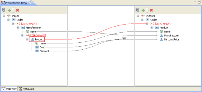
Figure 6: For-Each Mapping
This mapping specifies that for each Product element in the input XML, the output XML contains a Product element. For-Each mapping can be applied only to [ZERO-MANY] or [ONE-MANY] control nodes in the Output Structure. To create a For-each mapping in the Funclet Wizard, you need to link the Loop output label of the Input Structure node to a [ZERO MANY] or [ONE-MANY] control node in the Output Structure. These control nodes signify the cardinality of contained elements and attributes.
All value mappings for the attributes and child elements of a [ZERO MANY] or [ONE-MANY] node with For-Each mapping are carried out within the For-Each context.
So, in the above figure, the mapping defined creates multiple instances of the Product element from the Product elements in the Input Structure. The Output element, Product, is created as per the mappings defined for its attributes and child elements by the respective Name-to-Name mappings.
Duplicating a For-Each Mapping
There may be situations in which one may want to specify different input values for different iterations of a For-Each loop. This can be accomplished by duplicating a [Zero Many] or [One Many] control node in the output structure.
The following example illustrates this situation. A Student DTD has two types of child elements: male and female. These need to be mapped to the student element in the output structure DTD.
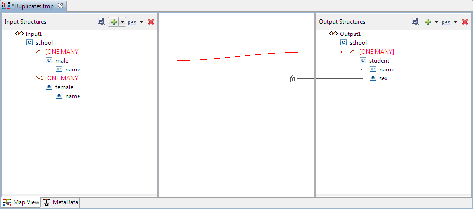
Figure 7: Mapping a node to One Many control node
The same mapping has to be defined for the female elements. To do this, drag the female node from the input structure to the ONE MANY node in output structure. A message dialog box is displayed in the figure below.
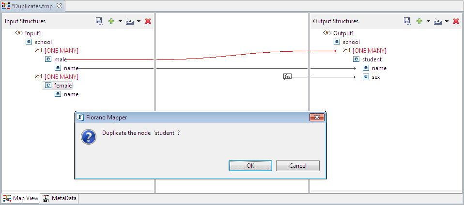
Figure 8: A shortcut menu prompts you to duplicate the node
Click OK in the message dialog box to create a duplicate node. A mapping is created as shown in the figure below.
If the replicated node does not appear, right-click ONE MANY in the Output Structures panel and click Expand All option.
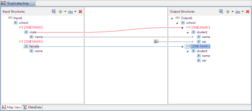
Figure 9: The One Many Node is Duplicated
Linking Nodes to Define Mappings
A Mapping is defined in the Fiorano eMapper tool by visually linking the Input Structure nodes to the Output Structure nodes. This linking can be defined using any of the following techniques:
- Drag and drop the node from the Input Structure Panel to the Output Structure Panel.
- Create an automatic mapping between child nodes of the selected Input Structure node and child nodes of the selected Output Structure node.
- Using the Visual Expression Builder.
Using the Automatic Mapping option to Define Mappings
To create automatic mappings between the selected Input and Output Structure nodes, perform the following steps:
Select the nodes in the Input and Output Structure whose child nodes are mapped. Click the Child to Child option in the tool bar.
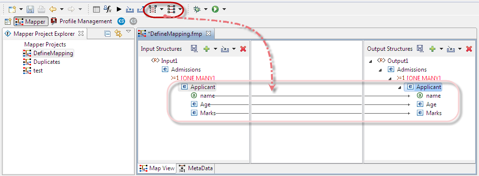
Figure 10: Creating Automatic Mapping between child nodes
Using the Visual Expression Builder to Define Mappings
The Visual Expression Builder (VEB) is a useful feature of the eMapper tool. It allows you to visually link nodes and insert functions to define complex mapping expressions. As an example, we define a mapping for the DiscountPrice output node. This node should have a value that is generated by subtracting the value of the Discount input node from the Cost input node. To use the VEB to define the mapping, perform the following steps:
- Select the DiscountPrice output node, the Funclet View of the eMapper Perspective appears.
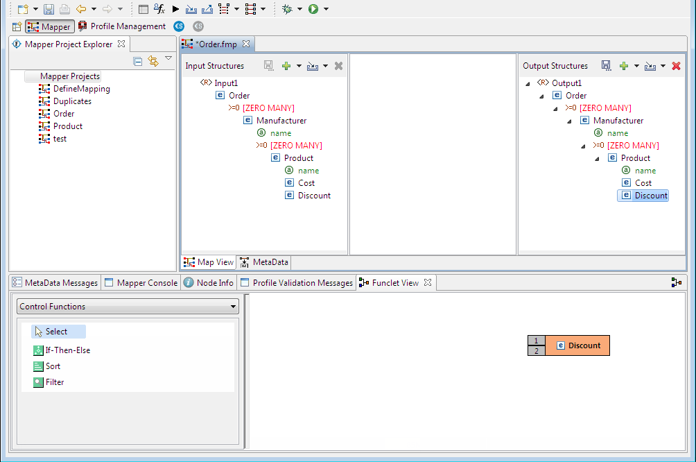
Figure 11: Selecting the Output Node for Mapping
- The selected Output node is automatically displayed in the Function easel, as shown in the figure above. To add an input structure node to the mapping, drag it to the Funclet easel of the Visual Expression Builder. Here, drag the Cost input node from the Input Structure Panel to the Funclet easel. The Cost input node is added to the Funclet easel as shown in the figure below.
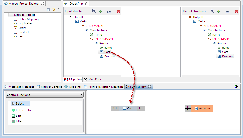
Figure 12: Dragging an Input node
- To subtract the value of Discount input node, the subtract function from the Funclet Palette can be used. The subtract function is available in the Arithmetic functions. To add the subtract function, click on the drop-down list in the Funclet palette and select the Arithmetic Functions from the list. The drop-down list is displayed in the Funclet palette as shown in the figure below.
- The Arithmetic functions are displayed in the Funclet palette. Drag the subtract function from the Function palette to the Funclet easel. The subtract function is added to the Funclet easel as shown in the figure below.

Figure 13: Selecting the Arithmetic Function Category in the Funclet palette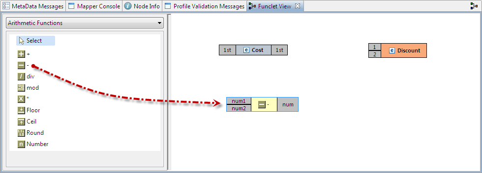
Figure 14: Adding the Subtract function
Add the Discount input node to the Funclet easel.
Move the Subtract function to place the Discount input node parallel to Cost node to form a neat layout.

Figure 15: Adding another input node
- To define a mapping, links should be defined between these nodes. The Discount output is the difference between the Cost and Discount input nodes. To achieve this, the Cost and Discount nodes should be connected to the input pins (num1 and num2 respectively) of the subtract function and its output pin should be connected to the input pin of the Discount output node.

Figure 16: The final mapping is defined
- The required mapping is defined as shown in the figure above.
Mapping XML Formats
Mapping one XML format to another is a common requirement. The steps for mapping XML, formats to each other are as follows:
- Load the XML, DTD, or XSD input structure or structures.
- Load the XML, DTD, or XSD output structure.
- Link the Input XML Structure node(s) to the Output XML Structure node.
The following restrictions and conditions apply when mapping one XML format to another:
- Nodes that do not have any content cannot be mapped. However, the child nodes of these nodes can be mapped provided they can contain content.
- The SQL and advanced function categories are not available for XML to XML mapping.
